2017年4月22日 星期六

2016資優營第一天

一小時玩程式(Hour of Code™ in Taiwan)

http://hocintw.thealliance.org.tw/

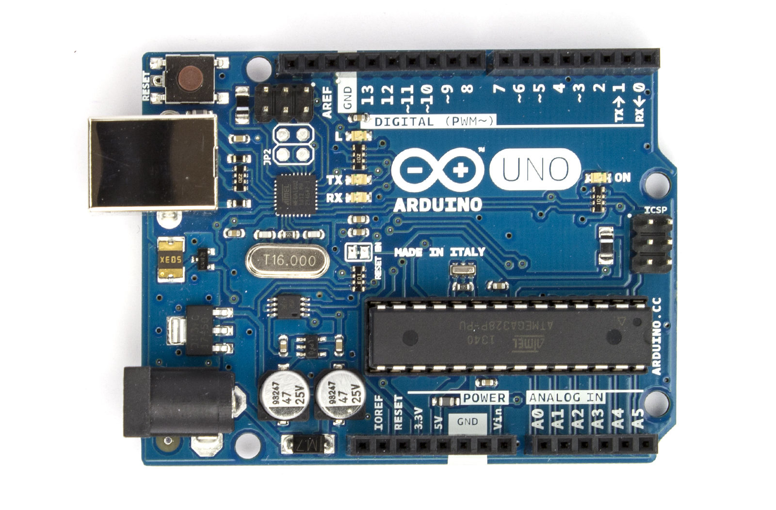
Arduino 板子

IO擴充板  V4    V5   V5

Arduino 程式下載


使用程式 Arduino 1.8.2
檢測板子
使用 範例程式 01basic -->blink
確認 工具 開發板 是否選擇 arduino UNO
確認 工具 序列埠 是否選擇 正確

使用紅綠燈模組
模組GND  連接 擴充板上的 G
模組R 是紅燈  連接 擴充板上的 S4
模組Y 是黃燈  連接 擴充板上的 S5
模組G 是綠燈  連接 擴充板上的 S6
修改 Blink 使得紅燈會亮

作業:
改成黃燈 每一秒 閃 3下

==================================================
呼吸燈
使用 範例程式 01basic --> Fade
修改 第16行程式碼 int led = 6;


作業:
試試看 紅色跟黃色 在不修改硬體連接的情形下可以嗎?
為什麼?

觀念:
PWM 模擬類比輸出
變數

===============================================
交替的呼吸燈
增加一個新的變數 ledY
analogWrite(ledY, brightness);


===============================================
類比可變電阻輸入
模組G  連接 擴充板上的 G
模組V  連接 擴充板上的 V
模組S  連接 擴充板上的 A0
使用 範例程式 01basic --> AnalogReadSerial
打開  序列埠監控視窗
觀察旋轉可變電阻的結果


===============================================
用紅黃綠來顯示可變電阻的位置
使用 範例程式 07Display -->bargraph
< 120度時 不亮
介於120到240之間 亮一顆燈
介於240到350之間 亮2顆燈
到底時 亮3顆燈

=================================
音樂
使用 範例程式 02Digital -->Melody
蜂鳴器接在 S8

執行結果

===================================
開關
使用 範例程式 02Digital -->Button

執行結果

======================================
觀念
數位輸出
類比輸出
數位輸入
類比輸入

======================================
製作一個燈光控制器
用可變電阻控制LED燈的亮度
使用三色LED模組

控制藍色LED
使用 範例程式 03Analog -->AnalogInOutSerial
修改成綠色或紅色
修改成白光或其他顏色


======================================
超音波測量距離
下載超音波模組  下載
草稿碼   --> 匯入程式庫  --> 加入ZIP程式庫
草稿碼   --> 匯入程式庫  --> 程式庫管理員 搜尋 HCRS04 安裝
解壓縮 將 Ultrasonic目錄 複製到 我的文件夾  Arduino Library目錄下

連接 超音波感測器的接腳
模組VCC 是連接 擴充板上的 V
模組TRIG 是連接 擴充板上的 S9
模組ECHO 是連接 擴充板上的 S8
模組GND  連接 擴充板上的 G

使用 範例程式 第三方範例程式 Ultrasonic --Serial 
觀察結果

=========================================


2015年12月19日 星期六

創意搖控自走車-第一天

Arduino UNO 加 感測器

程式下載             https://www.arduino.cc/en/Main/Software
UNO 板子介紹   http://coopermaa2nd.blogspot.tw/2011/05/arduino.html
                             https://www.arduino.cc/en/Main/ArduinoBoardUno

感測器擴充版  V4.0  https://arduino-info.wikispaces.com/SensorShield
感測器擴充版  V5.0  http://elesson.tc.edu.tw/md221/course/view.php?id=253 

37合一 感測模組       https://tkkrlab.nl/wiki/Arduino_37_sensors


2014年3月7日 星期五

L298N驅動板

美崙國中版本
http://arduino-info.wikispaces.com/MotorDrivers

Motor A 
int dir1PinA = 13;
int dir2PinA = 12; 
int speedPinA = 10;

motor B 
int dir1PinB = 11;
int dir2PinB = 8; 
int speedPinB = 9;

範例說明
 http://arduino-info.wikispaces.com/ArduinoShieldL298N


一般的


2014年1月20日 星期一

自走車機器人自我檢查步驟

一、確認連接線
         電源線 正負極性不可以接反
         伺服機排線的正負極與信號不可以接反

二、確認超音波端子頭
        確認超音波端子連接線是否接正確,正負極與TR、EC的連接。

三、接上USB端子。觀察電路工作狀態

四、啟動超音波程式,檢測超音波功能是否正確。

五、啟動伺服機控制程式

2014年1月8日 星期三

102下學期工作項目

填寫問卷
 https://docs.google.com/spreadsheet/viewform?formkey=dEFQcU1Ncy1qMzVBd05lc1ZWdnIwU0E6MQ

2月21日 參加自走車研習
2月23日 參加Arduino基礎模組研習
3月29日 參加花蓮區Arduino專題製作競賽
參加組別 高中組自走車  或  高中組創意賽
報告書 4月上旬繳交

參加聯合科大競賽(自費)

5月3、4日 參加 四二專統測

5月24、25日 參加台北 Make Faire活動(自費)

5月下旬 學校作品發表會

專題報告撰寫格式

期末報告參照格式
群科中心格式 

作品實際範例參考

2013年12月21日 星期六

選手小車驅動

下載
https://drive.google.com/file/d/0B_uh7-e5jDMcVHgwOHphNkFzeVk/edit?usp=sharing

伺服馬達校正
先使角度為 90度 再裝上超音波模組
// Controlling a servo position using a potentiometer (variable resistor)
// by Michal Rinott <http://people.interaction-ivrea.it/m.rinott>

#include <Servo.h>

Servo myservo;  // create servo object to control a servo

void setup()
{
  myservo.attach(5);  // attaches the servo on pin 9 to the servo object
}

void loop()
{
  myservo.write(90);                  // sets the servo position according to the scaled value
  delay(1500);                           // waits for the servo to get there
}

超音波

參考資料
http://coopermaa2nd.blogspot.tw/2011/05/arduino.html

超音波程式庫
http://wiki.tetrasys-design.net/HCSR04Ultrasonic


發出聲音

發出聲音
焊接板 改成 接腳 12

2013-12-21 花工假日樂活營課程

Arduino入門
範例一  閃爍燈:測試電路板
範例二  呼吸燈:學習 if
範例三  調控燈:學習類比輸入
範例四  霹靂燈:學習for 指令
任務一:結合範例一與二
任務二:結合範例三與四
使用網頁:

Cooper Maa
http://coopermaa2nd.blogspot.tw/2011/05/arduino.html

曹永忠老師網頁
http://www.cs.pu.edu.tw/~yctsao/indexdown.php

2013年11月9日 星期六

自強國中課程程式一 6燈改9燈

/*
  For Loop Iteration

 Demonstrates the use of a for() loop.
 Lights multiple LEDs in sequence, then in reverse.

 The circuit:
 * LEDs from pins 2 through 7 to ground

 created 2006
 by David A. Mellis
 modified 30 Aug 2011
 by Tom Igoe

This example code is in the public domain.

 http://www.arduino.cc/en/Tutorial/ForLoop
 */

int timer = 200;           // The higher the number, the slower the timing.

void setup() {
  // use a for loop to initialize each pin as an output:
  for (int thisPin = 2; thisPin < 11; thisPin++)  {
    pinMode(thisPin, OUTPUT);    
  }
}

void loop() {
  // loop from the lowest pin to the highest:
  for (int thisPin = 2; thisPin < 11; thisPin++) {
    // turn the pin on:
    digitalWrite(thisPin, HIGH);  
    delay(timer);                
    // turn the pin off:
    digitalWrite(thisPin, LOW);  
  }

  // loop from the highest pin to the lowest:
  for (int thisPin = 10; thisPin >= 2; thisPin--) {
    // turn the pin on:
    digitalWrite(thisPin, HIGH);
    delay(timer);
    // turn the pin off:
    digitalWrite(thisPin, LOW);
  }
}

2013年10月14日 星期一

使用Arduino UNO 燒錄ATMEGA8 實驗一

使用Arduino UNO 燒錄ATMEGA8

ATmega8-Arduino Pin Mapping (接腳圖)

   http://arduino.cc/en/Hacking/PinMapping?from=Main.PinMapping


參考下圖 連接於麵包板上


軟體操作程序:
使用軟體 ARDUINO 1.05
硬體 Arduino UNO R3

Step 1 : 將 Arduino  UNO 變成 ArduinoISP (上傳 ArduinoISP code 到 UNO板子上)
作法:
將  UNO 連接到 PC ,從選單  File -> Examples -> ArduinoISP and upload this sketch.
Step 2 : 燒錄 bootloader 到 Atmega8
作法:
連接 Atmega (Atmega8 ) to the UNO 板上 ,如上面電路圖所示.
從  選單 Tools -Board 選 Arduino NG or older w/ Atmega8
從  選單 Tools - programer 選 Arduino as ISP
最後  選單 Tools - Burn Bootloader
將 Bootloader燒到 Atmega8

Step 3: 驗證是否成功(將 Blink 範例燒入Atmega8)

作法:
將 Atmega328 從 UNO 板上取下,並且將麵包板上的 Atmega8 放到 UNO的IC座上
 ,請小心接腳不要弄錯  (兩顆IC 缺口要在相同的位置,取下IC前先確認或是查看 )。
並且在拔插IC時要拔下USB接頭讓電源關閉。
完成後 接上USB
從  選單      File – Examples – Basics – Blink  選擇  Blink範例
從  選單       Tools -Board – NG or older w/Atmega8   板子設定
再次確認 COM埠值(會不一樣)
燒錄
稍帶片刻 UNO 板上的 第13腳 LED 會閃表示正常。

Step 4 : 將Atmega8  移回麵包板上,觀察是否正常。

移除上圖黃色與綠色的線,保留其餘連線如下圖
在IC的第19腳接上 220歐姆電阻串聯LED 到 5V端,查看是否LED會閃爍.如下圖。
在拔插IC時暫時中斷電路電源。
另外在 Nirzaree's Blog 中對於UNO PIN13 對應寫錯 應該是 ATMAGE 8的第 19 腳。 


任務成功。


參考網頁

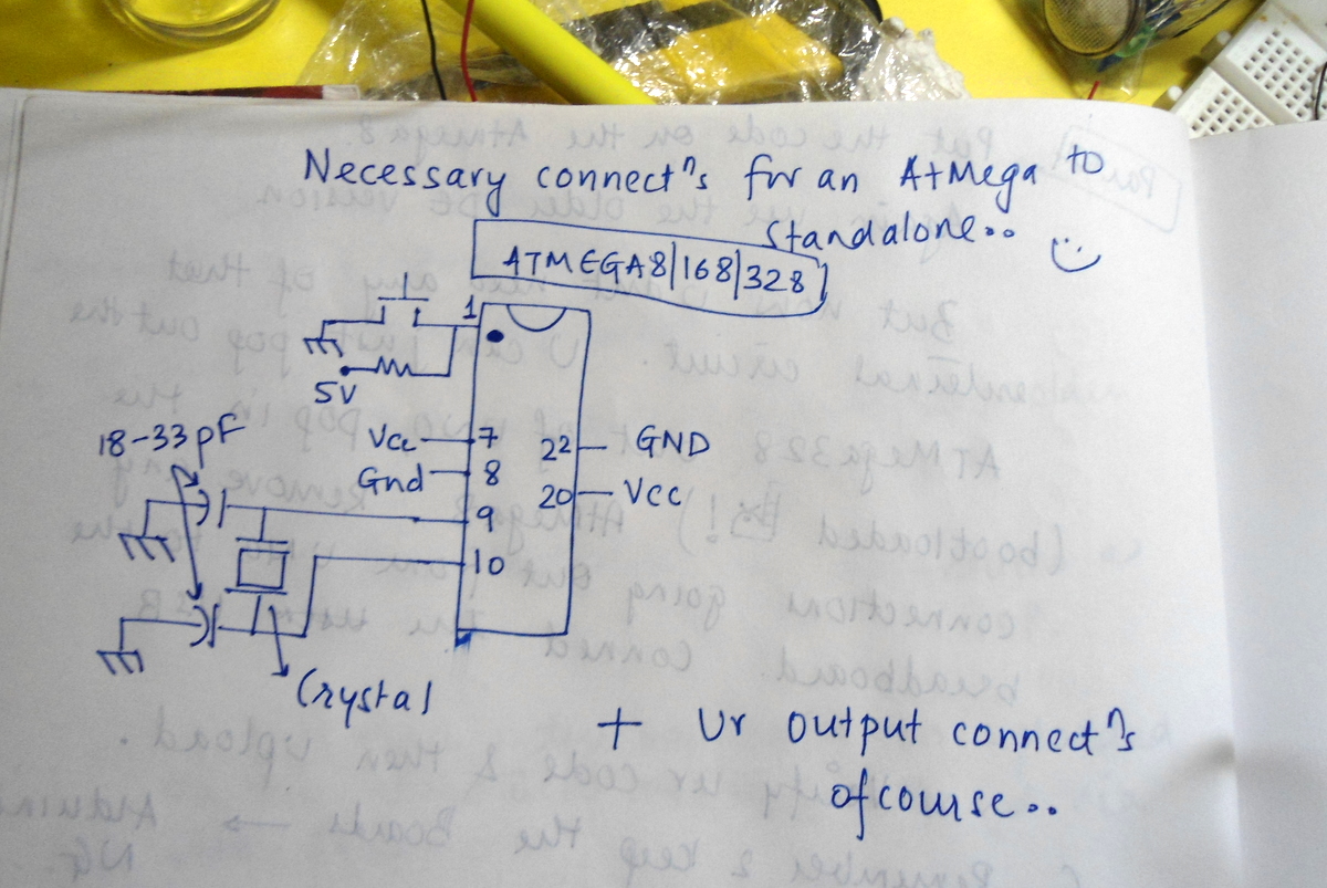
 Nirzaree's Blog Make a standalone Atmega8 circuit
http://nirzaree.wordpress.com/2012/03/07/make-a-standalone-atmega8-circuit/

GROBO 

DIY Arduino - 將Bootloader寫進ATMega晶片